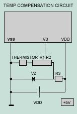
TEMPERATURE COMPENSATION High Temperature Increasing temperature changes some physical properties of the LC material, especially the anisotropy of the refractive index, which is responsible for STN-LCD operation. This changes the background color from yellow-green to blue at temperature above 50°C. The result is a decrease of the characteristic excellent contrast of STN, but even at temperature up to 70°C the readability is not completely lost. This effect is reversible, and after cooling, the display returns undamaged to its original state. Low Temperature Lower temperature also results in a change of the background color to red-orange for STN-LCD. There is almost no change in the contrast, but the switching times are increased significantly as is well known for the standard TN-display. Air bubbles may form at very low temperature (below -20°C) due to the large temperature dependent shrinkage of the liquid crystal material. But this behavior is reversible without damage to the cell. Temperature Compensation LCD modules have a limited operating temperature range. The fluid within the glass is the most limiting factor. Threshold voltage and viewing angle are temperature dependent. Temperature compensation of the driving voltage is necessary to have good contrast and viewing angle of the operating temperature range. This temperature compensation circuits depend on the physical properties of the dV/dT parameter which varies from 8 to 22 mV/°C-1 depending upon the fluid and duty rate. Over the rated range, the bias, or VO voltage required to optimize the contrast and maintain a constant viewing cone varies slightly. Compensation or adjustment can be achieved manually, with a temperature compensation circuit, or a combination of both. Manual adjustment involves user accessible control via a potentiometer or digital device. A standard, negative temperature coefficient thermostat serves as an inexpensive, automatic sensor. It should be mounted as close to the glass as possible to get an accurate measurement. A thermistor circuit can be configured to provide automatic temperature compensations. Each module's specification lists approximate VO voltages required at the extremes of the temperature range and at 25C. A suggested circuit is shown below. When operating outside of the module's rated temperature range, forced air and/or a heater are required to maintain reliable operation. The heater manufacturer can offer design assistance.
|
|
| Glossary | LCD Module | LCD Panel | Backlight | IC | Top |
 Note:
Note: