|
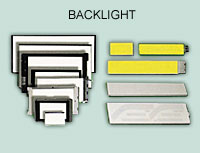
LED BACKLIGHT
Features
- LED backlit modules are 2-5mm thicker than an EL or non-backlit
module.
- Longer life ( more than 100,000 hours ) than EL lamps at the
sacrifice of power and module size.
- Operation is possible by the same +5 V supply as used for the
modules. (Standard color yellow-green)
- The LED backlight illumination is available in yellow-green,
green, white, red, and amber.
- The brightness of the backlight can simply be adjusted by a
resistor or a potentiometer
- In most cases, 1 lamp failing does not make the backlight unusable.
Using Methods of BKL
There are 5 methods of using LED in character type:
- This is the most common type to light the LED by external of
4.2V to Jp2 between pin 1 and pin 4.
- Lighting the LED through a limiting current resistance which
we already included in our LCM by external voltage of 5V to Jp2
between pin 1 and pin 4.
- Providing 4.2V by pin 15 and pin 16 of the interface to light
LED.
- Providing 5V by pin 15 and pin 16 of the interface to light
the LED through a limiting current resistance which we already
included in our LCM.
- We can light the LED only by inner voltage through a limiting
resistance without any external power supply.
 Resistors
for LED Backlight Resistors
for LED Backlight
Limit resistors must be used for array backlit modules. Refer
to the specific module specification for recommended and/or maximum
backlight ratings. LEDs are arranged in serial pairs and operated
in parallel . The lamp will require 4.2VDC. Brightness can be
set or controlled by selecting the proper limit resistor. Select
a resistor that will drop the remaining voltage at the desired
current. For example, if 200mA produces the desired brightness
and the supply voltage is +5VDC, the limit resistor will drop
0.8VDC (5.0 - 4.2). Therefore, E/I = R = 0.8/0.2 - 4ohms.
Variable brightness can be controlled with a digital potentiometer
or pulse-width modulated circuit.
|